Position control with the web client
Position control moves a motor to an encoder angle. Its PID produces a requested speed, and the separate velocity PID produces motor PWM. Tune and initialize velocity control first; then initialize position.
Position target → position PID → speed target → velocity PID → motor PWM
                       ↑                            ↑
                 encoder angle                encoder speed
The two controllers have independent Kp, Ki, and Kd settings. Position gains cannot replace velocity gains: their outputs have different units. This tutorial uses firmware 2.3.1; full position PID setup requires firmware protocol 2.3 or newer.
1. Connect and choose your units
Connect your controller by USB, power the motor supply, and open the Kinisi web client in desktop Chrome or Edge. Click Connect, select the controller, and check its firmware version on Connection. See the connection guide for details.
Keep the mechanism's entire travel clear and Stop motor controller within reach.
Open Settings and choose radians or degrees under Angle units. Select Degrees (deg, deg/s) to follow the degree values below.

The choice applies to angular targets, feedback, limits, and graphs on every page and saves automatically in this browser. Kp, Ki, and Kd do not change: the firmware calculates with radians internally. PWM percentages, encoder tick counts, and platform distances in meters also stay unchanged.
For reference, 1 rad = 57.296° and 1 rad/s = 57.296°/s.
2. Prepare the motor and encoder
Open Motor Controller and complete the motor, encoder, loop frequency, and velocity PID setup in the velocity tutorial. Initialize velocity control before position control. For the recorded demo, the prerequisite configuration was:
| Setting | Demo value |
|---|---|
| Motor / encoder | 0 / 0 |
| Encoder resolution | 1425.1 ticks per output-shaft revolution |
| Controller frequency | 20 Hz |
| Velocity Kp / Ki / Kd | 5 / 30 / 0.2 |
| Velocity integral contribution limit | 100% PWM |
Use settings suited to your motor, gearing, load, and travel limits. Confirm that positive speed produces positive encoder feedback, then command zero speed before position initialization.
3. Initialize position control
On Motor Controller, scroll to 2. Position control. The green Velocity controller initialized message confirms the prerequisite.
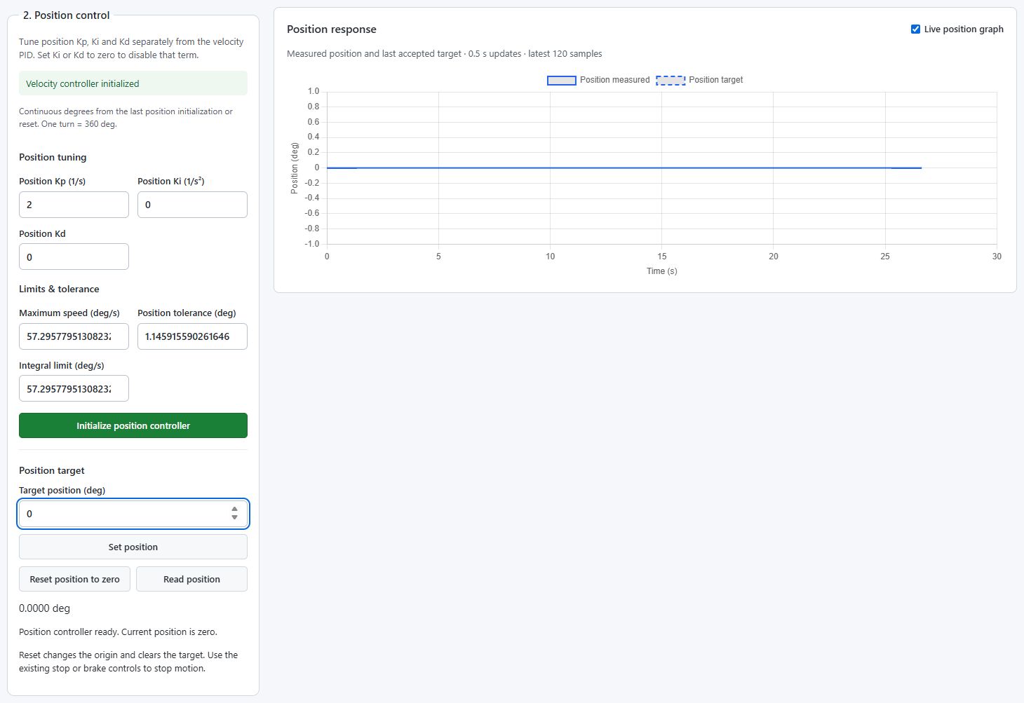
Enter these values to reproduce the demo configuration:
Parameters
| Field | What it does | Units | Demo value |
|---|---|---|---|
| Position Kp (1/s) | Converts position error into an immediate speed contribution | 1/s | 2 |
| Position Ki (1/s²) | Accumulates position error into a speed contribution over time | 1/s² | 0 |
| Position Kd | Responds to changes in position error | Unitless | 0 |
| Maximum speed | Caps the magnitude of the requested speed | deg/s or rad/s | 57.2958°/s (1 rad/s) |
| Position tolerance | Defines the acceptable remaining angle error | deg or rad | 1.1459° (0.02 rad) |
| Integral limit | Caps the magnitude of the I contribution alone | deg/s or rad/s | 57.2958°/s (1 rad/s) |
These values were used with our motor and 30 cm arm. They are a worked example, not a universal motor profile. Gains stay the same in either angle unit; the client converts angular limits and tolerance for you.
Click Initialize position controller. For a motor, its current encoder angle becomes zero. The controller is ready for a target; initialization does not command a move.
How the PID calculates output
The simplified position calculation outside the tolerance is:
error = target angle − measured angle             (rad)
P = Kp × error
I = accumulated Ki × error × elapsed time, bounded to ± integral limit
D = Kd × filtered rate of change of error
requested speed = clamp(P + I + D, −maximum speed, +maximum speed)  (rad/s)
The firmware filters the derivative and uses anti-windup when the requested speed saturates. The separate velocity PID turns this speed request into PWM.
Proportional (Kp): responds to the current position error. At Kp = 2, an error of 10° contributes 20°/s. With Ki and Kd at zero, this is the requested speed until the speed limit applies. Kp is the gain; the P contribution decreases as the motor approaches the target.
Integral (Ki): builds a speed contribution while position error persists. For example, Ki = 1 with a steady error of 0.1 rad adds 0.1 rad/s to I per second, until a limit or anti-windup intervenes. Keep Ki at zero initially; add it cautiously if an offset outside tolerance remains after velocity tracking is tuned.
Derivative (Kd): responds to changes in position error to add damping. The firmware filters this term, but too much Kd can still make encoder noise affect the requested speed. Unlike velocity PID, it differentiates error, so a new position target can also affect this contribution. Zero disables it.
What the limits mean
Integral limit bounds the I contribution alone, in deg/s or rad/s. With a 1 rad/s integral limit, I can contribute from −1 to +1 rad/s. P, I, and D are added before the final speed cap. This is different from velocity PID's % PWM limit. A limit of 0 disables integral action, even if Ki is nonzero.
Maximum speed caps the position controller's requested velocity. It is not an acceleration limit or a trajectory profile. Actual shaft speed depends on the velocity loop and mechanics; lowering it alone does not guarantee smooth motion.
Position tolerance defines the acceptable remaining angle error. Inside that tolerance the position loop requests zero speed and clears its PID history. This is not a mechanical brake or a guaranteed holding torque.
4. Set a target and read the graph
Under Position target, enter 90 in Target position (deg) and click Set position. Observe the mechanism and the Position response graph. Wait until measured position settles near the target before sending the next one.
Repeat with 180, then 360, then 0. These are absolute angles relative to the current origin, not additional movements. Sending 180 after 90 asks for another quarter-turn. Sending 0 after 360 asks it to return through one full turn.
Motor angles are continuous: 0° and 360° are different targets. The motor does not wrap them onto the same angle. The firmware uses radians internally; the client converts your degree input before sending it.
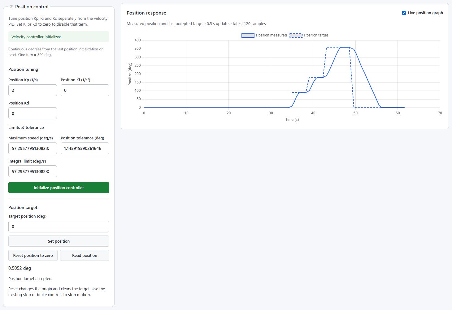
The solid trace is measured encoder position and the dashed trace is the last accepted target. The graph samples approximately every 0.5 seconds and keeps 120 samples. A target acceptance message means the command was accepted, not that the motor has already arrived.
In the recorded run, the final encoder readings were:
| Target | Measured angle |
|---|---|
| 90° | 89.6779° |
| 180° | 179.1032° |
| 360° | 359.4695° |
| 0° | 0.5052° |
All four readings were within the configured 1.1459° tolerance. These results describe this setup and run; they do not guarantee the same accuracy on another mechanism.
5. Stop or reset
Read position requests the latest measured angle. Reset position to zero makes the present encoder angle the new zero and clears the target. It does not move the shaft back to the original zero and should not be used as a stop button.
To return to the original zero, send a 0 target before resetting the origin. To stop and remove control, use Stop motor controller. Initialize velocity and then position again to resume. Sending a velocity target overrides position mode; send a new position target to return to position control while its setup remains valid.
After motor/encoder or velocity-controller reinitialization, repeat position initialization. It establishes a new motor origin. The origin is encoder-relative, not a homing reference saved across a controller restart.
Tune the controller
First check velocity tracking. Surging or jerky speed in the inner loop carries through to position motion. With velocity stable, tune one position gain at a time:
- Begin with Ki and Kd at zero. Adjust Kp for the approach and choose a suitable speed limit. Reduce Kp if the motor oscillates or overshoots.
- Add Ki cautiously if a persistent offset outside tolerance remains. Excessive Ki can cause overshoot or repeated corrections.
- Add a small Kd only if damping helps. Reduce it if the requested speed becomes noisy.
- Repeat at several targets and in both directions with the intended load.
Choose a tolerance that makes sense for encoder resolution and mechanical backlash. Apply changed settings with Initialize position controller, remembering that this sets the motor origin again.
Watch the demo
Motor 0 moves a 30 cm arm to 90° → 180° → 360° → 0°. The camera runs continuously, with the web client and a synchronized replay of the recorded position graph beside it.
Platform control
The Platform page uses the same two-loop idea for the whole robot:
- Initialize the platform geometry and motor/encoder directions.
- Initialize its velocity controller and verify motion tracking.
- Turn off keyboard driving, then initialize position control.
- Wait for fresh odometry before setting a position target.
Platform targets are absolute world-frame X/Y in meters and heading in radians or degrees relative to the odometry origin. Translation Kp/Ki/Kd tune X/Y motion; Heading Kp/Ki/Kd tune rotation. Their integral limits are respectively m/s and rad/s or deg/s. Maximum translation and rotation speeds and the two tolerances are configured separately. Degree/radian Settings affects heading values, angular speed limits, and angular integral limits; it does not change the gains or meter values.
Mecanum and omni platforms can translate sideways. A differential platform turns toward the destination, drives toward it, then finishes at the requested heading. Platform odometry estimates pose from wheel encoders, so slip and geometry errors affect the result. A platform origin reset clears the target; wait for fresh odometry afterward. See the platform overview for setup.