Web Client
The Kinisi web client is a browser app for driving a Kinisi Motor Controller straight from your computer — no install, no SDK, no code. It is useful for bringing a new board up, checking wiring and motor direction, tuning PID gains, and driving a platform around before you write any software against it.
The client talks to the board over USB using the browser's Web Serial API. Everything runs locally in your browser; nothing about your board is sent anywhere.
Source code: vsreality/jskinisi.
For guided setup with current screenshots and a real motor demo, start with velocity control, then follow position control.
Before you start
- A Chromium-based desktop browser — Chrome, Edge, or Opera. Firefox and Safari do not implement Web Serial, and neither do mobile browsers.
- The controller connected to your computer with a USB cable.
- Motors powered from the controller's motor supply, if you intend to spin them.
Motors run as soon as you command a speed. Put the robot on blocks, or make sure the wheels are clear, before setting a speed for the first time.
Connecting
Open kinisiclient.vsreality.com and press Connect.
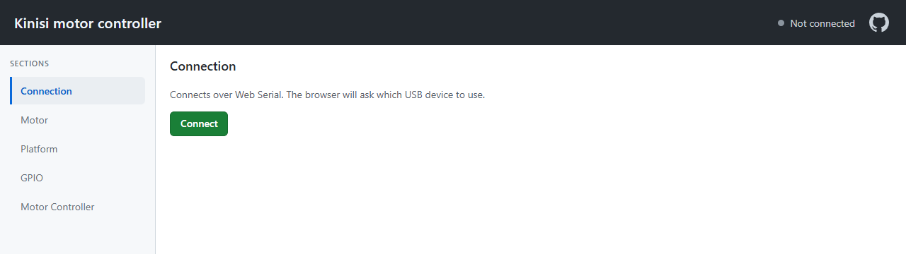
The browser then shows its own device picker listing the serial ports it can see. Choose the Kinisi controller and confirm. The client never sees any device you do not pick.
Once the link is up:
- The header shows a green Connected indicator, visible from every section.
- The sections in the left sidebar unlock, and the client opens Motor for you.
- Reconnecting later reopens whichever section you were last working in.
- The Connection page reports board and firmware versions.
To finish, go back to Connection and press Disconnect. Disconnecting is not just a hang-up: the client stops the platform controller, removes all four motor controllers, and stops all four motors first, so the robot does not carry on running with the page closed.
The controller keeps applying the last command it received. If you set a speed and then close the tab without disconnecting, the motors keep turning.
Motor — direct control
The Motor section drives a single motor open-loop and reads its encoder. It is the quickest way to confirm that a motor is wired correctly and that its encoder counts in the right direction.
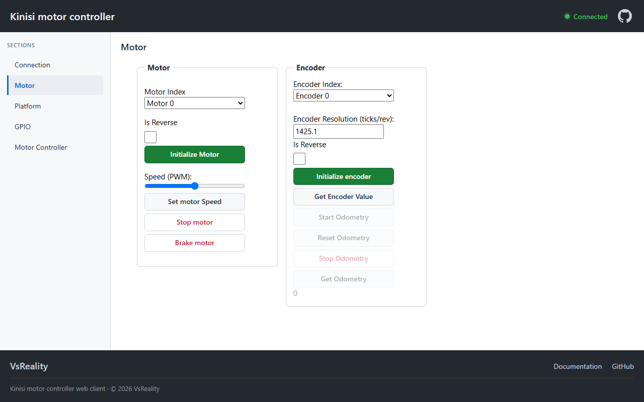
Motor
- Motor Index — which of the four channels (0-3) the controls act on.
- Is Reverse — flips the motor's direction, so you can fix a swapped pair of motor leads in software instead of rewiring.
- Initialize Motor — configures the channel with that direction.
- Speed (PWM) — duty cycle from -100 to 100. Set motor Speed applies it (initializing the motor first if needed).
- Stop motor — sets the motor's speed to zero.
- Brake motor — engages the brake, bringing the motor to a stop far more sharply than simply commanding zero.
Encoder
- Encoder Index and Encoder Resolution (ticks/rev) — the resolution is ticks per revolution of the wheel, so on a geared motor it is the count at the output shaft rather than at the motor itself. The default, 1425.1, matches the geared motors used on the reference platforms.
- Initialize encoder — applies the resolution and direction.
- Get Encoder Value — reads the raw tick count.
- Start / Reset / Stop / Get Odometry — unlock once the encoder is initialized, and turn the tick count into distance travelled by that wheel.
If the encoder counts down while the wheel drives forward, tick the encoder's own Is Reverse and initialize it again.
Motor Controller — closed-loop speed
The Motor Controller page has separate velocity and position controls. Configure Motor & encoder and Loop frequency, then enter Kp, Ki, Kd, and the Integral contribution limit (% PWM) under 1. Velocity control. Press Initialize velocity controller, choose a Speed target, and press Set velocity target. The limit bounds I alone from 0–100 PWM percentage points; total PWM is capped at ±100%.
Velocity response plots measured and target speeds, with speed error available through the legend. The graph updates approximately every 0.5 seconds; the firmware loop frequency is set separately. Reset velocity PID clears the PID history and sets its target to zero. Stop motor controller stops the motor and removes its controller.
Follow the velocity tutorial for screenshots, the PID calculation, and a tuning walkthrough.
Motor Controller — position
Once velocity control is initialized, 2. Position control configures a separate position Kp/Ki/Kd, maximum speed, tolerance, and integral speed limit. Press Initialize position controller to establish the current shaft angle as zero, then enter an absolute target and press Set position.
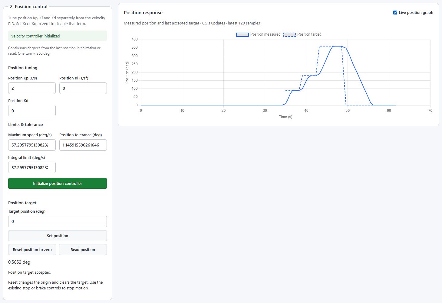
Motor position is continuous relative to its origin: 360° means one complete turn from zero. Reset position to zero moves the origin to the present encoder angle and clears the target; it does not command a return to the old zero. See the position tutorial for the 90° → 180° → 360° → 0° demo and the difference between the two PID loops.
Settings — angle units
Choose Radians or Degrees under Settings → Angle units. It applies to angles and angular speeds on all pages, including targets, feedback, graphs, and angular limits, and saves automatically in this browser. Kp/Ki/Kd, PWM percentages, and values in meters remain unchanged. Firmware commands continue to use radians internally.
Platform — driving the whole robot
The Platform section treats the wheels as one vehicle, so you command the robot's motion rather than individual motors.
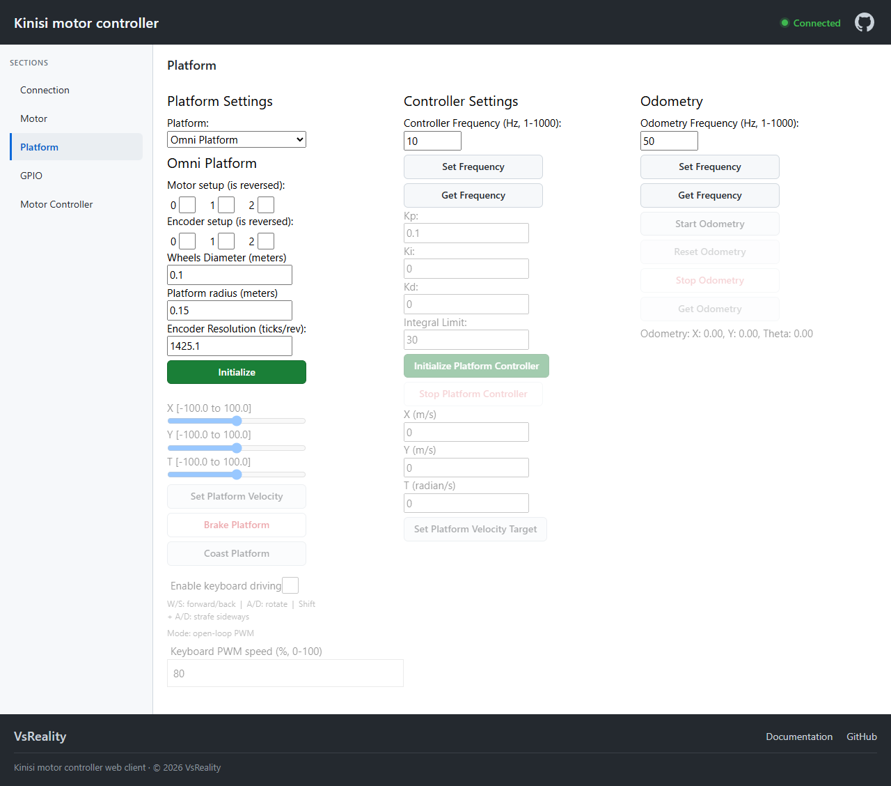
Platform Settings — choose Mecanum, Omni or Differential, mark any reversed motors and encoders, enter the geometry (wheel diameter, and the platform's length and width, radius, or wheel base depending on the type) and the encoder resolution, then press Initialize.
Open-loop driving — the X, Y and T sliders command forward,
sideways and rotational motion as PWM percentages from -100 to 100. The
platform uses a REP-103 right-handed
frame, so +X is forward, +Y is left, and +T rotates counter-clockwise.
Set Platform Velocity applies them. Brake Platform holds the wheels
against motion; Coast Platform lets them spin down freely. Both also stop
the velocity controller if one is running.
Keyboard driving — tick Enable keyboard driving to steer with the
keyboard: W/S forward and back, A/D rotate, and Shift + A/D to
strafe sideways on a platform that supports it. It drives open-loop in PWM
until you start a platform controller, and in real velocity units afterwards.
1. Velocity control — configures the wheel velocity PID. Once Initialize velocity controller has run, the target boxes take real units: meters per second for X and Y, radians or degrees per second for heading according to Settings.
2. Position control — adds independent translation and heading PID gains, speed limits, integral speed limits, and tolerances. Initialize velocity first, turn off keyboard driving, initialize position, and wait for fresh odometry. Targets are world-frame X/Y in meters and heading in the selected angle unit. See platform position setup.
Odometry — set the update frequency and press Start Odometry; Get Odometry then reports the platform's estimated position as X, Y and Theta. Reset Odometry returns that estimate to zero, which is handy at the start of a run.
GPIO
The GPIO section exercises the board's eight general-purpose pins and the status LED — a quick way to test limit switches, endstops and indicators.
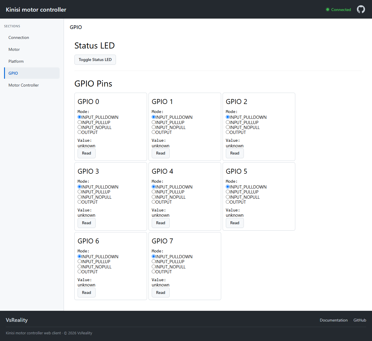
Each pin has four modes: INPUT_PULLDOWN, INPUT_PULLUP, INPUT_NOPULL and
OUTPUT. Picking a mode configures the pin on the board immediately.
- Input pins show a Read button and the value last read.
- Output pins show a slider that switches the pin between 0 and 1.
Toggle Status LED flips the controller's on-board LED, which is a fast way to confirm you are talking to the board you think you are.
Where to next
Every control in the client maps onto a command in the serial protocol, so
anything you can do here you can also do from your own software. See the
command documentation for the full
protocol, or the Python library examples
to script the same operations with pykinisi.