Velocity control with the web client
Velocity control makes a motor track a requested speed using encoder feedback. You enter an angular speed, and the controller adjusts PWM as the load changes. This is also the inner loop used by position control.
This tutorial uses the Kinisi web client and firmware 2.3.1. Use this firmware or newer for the PID behavior described here; older firmware needs different tuning.
1. Connect and choose your units
Connect your controller by USB, power the motor supply, and open the web client in desktop Chrome or Edge. Click Connect, select the controller in the browser's device picker, and check the firmware version on Connection. See the connection guide if this is your first use.
Keep the mechanism clear while tuning. Begin with a modest target speed and keep Stop motor controller within reach.
Open Settings and choose radians or degrees under Angle units.

The choice applies to angular targets, feedback, limits, and graphs on every page. It saves automatically in this browser. Kp, Ki, and Kd do not change: velocity PID always calculates with rad/s internally. PWM percentages and encoder tick counts also stay unchanged.
For reference, 1 rad/s = 57.296°/s. The firmware receives radians even when you enter degrees in the client.
2. Prepare the motor and encoder
Open Motor Controller. Under Motor & encoder:
- Select the motor channel, such as Motor 0.
- Select the encoder connected to that motor, such as Encoder 0.
- Enter the encoder Resolution (ticks/rev) at the controlled output shaft. The demo uses 1425.1; use the resolution of your own motor and gearing.
- Set Reverse motor and Reverse encoder as needed. A positive motor command must produce positive measured encoder speed.
If you are unsure of the encoder wiring, use the Motor page to initialize the encoder and read Get value while turning the shaft by hand. The count should change consistently. Correct the wiring or direction before closed-loop operation: feedback with the wrong sign can drive the output toward its limit.
Under Loop frequency, enter 20 and click Set Frequency for the demo configuration. Get Frequency reads it back. This is a global firmware loop setting shared by all controllers, not the graph refresh rate. The supported range is 1–1000 Hz; the highest value is not automatically best for a particular encoder and motor.
3. Initialize velocity control
Enter the gains under 1. Velocity control, then click Initialize velocity controller. This configures the motor and encoder and starts the velocity controller with zero output.
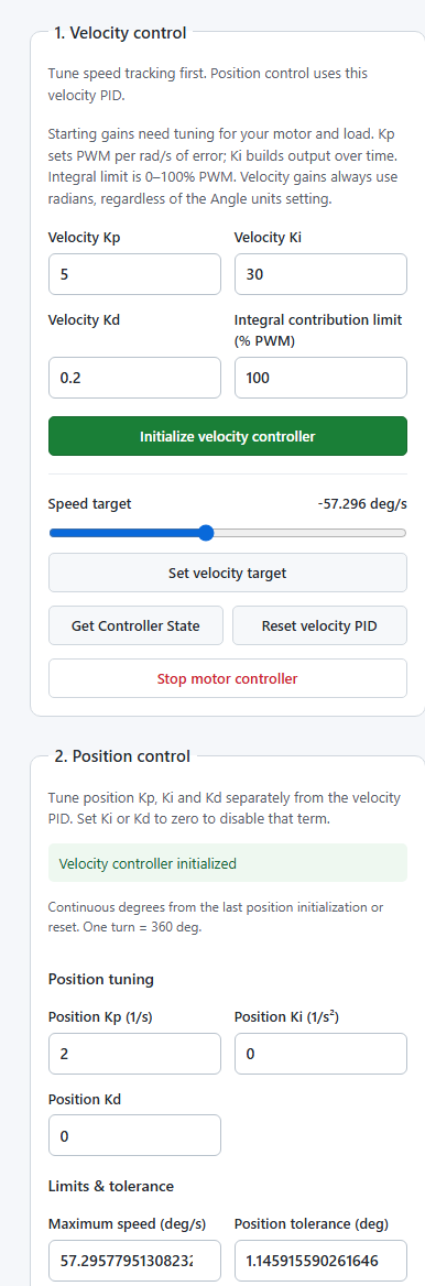
Parameters
| Field | What it does | Units | Demo value |
|---|---|---|---|
| Velocity Kp | Converts speed error into an immediate PWM contribution | PWM percentage points per (rad/s) | 5 |
| Velocity Ki | Accumulates speed error into a PWM contribution over time | PWM percentage points per rad | 30 |
| Velocity Kd | Responds to changes in measured speed | PWM percentage points per (rad/s²) | 0.2 |
| Integral contribution limit (% PWM) | Caps the magnitude of the I contribution alone | PWM percentage points | 100 |
These values were used with our motor and 30 cm arm. They are a worked example, not a universal motor profile. After changing gains, click Initialize velocity controller again to apply them. Reinitialization also invalidates position setup, so initialize position again if you were using it.
How the PID calculates output
The simplified velocity calculation is:
error = target speed − measured speed            (rad/s)
P = Kp × error
I = accumulated Ki × error × elapsed time, bounded to ± integral limit
D = filtered response to changes in measured speed
PWM = clamp(P + I + D, −100, +100)                (% PWM)
The actual firmware uses trapezoidal integration, a filtered derivative on measurement, and anti-windup when the total PWM saturates.
Proportional (Kp): responds to the current speed error. At Kp = 5, an error of 0.5 rad/s contributes 2.5 PWM percentage points. Kp is the gain; the P contribution changes as the error changes.
Integral (Ki): builds output while an error persists, helping overcome friction or load. For example, Ki = 30 with a steady error of 0.1 rad/s adds 3 PWM percentage points per second, until a limit or anti-windup intervenes. Start at zero when tuning P, then add I gradually.
Derivative (Kd): responds to changes in measured speed to add damping. The firmware filters this term and uses measurement rather than error to avoid a kick when the target changes. Too much Kd can amplify encoder noise. Zero disables this contribution.
What the limits mean
A 30% integral limit means I can contribute from −30 to +30 PWM percentage points. It does not cap the total output at 30% or prevent it reaching 100%: P, I, and D are added before the final ±100% cap. The limit defaults to 100 and accepts 0–100. 0 disables integral action, even if Ki is nonzero.
4. Set a target and read the graph
Move Speed target to a modest positive speed, then click Set velocity target. Moving the slider alone does not send a command.
With Live velocity graph enabled, Velocity response shows measured speed and target speed. Select Speed error in the legend to show the error. The client updates approximately every 0.5 seconds and retains the latest 120 samples; the firmware continues controlling between those reads.
5. Stop or reset
Set the target to 0 and click Set velocity target to command zero output while leaving the controller initialized. A velocity command also cancels active position mode.
Reset velocity PID clears the PID history and returns its velocity target to zero. Stop motor controller stops the motor and removes its controller; initialize it again before continuing. Use Connection → Disconnect when finished rather than simply closing the browser tab.
Tune the controller
Tune one gain at a time:
- Begin with Ki and Kd at zero. Increase Kp gradually until the response is useful, then reduce it if the speed oscillates.
- Add Ki gradually when measured speed remains below or above the target. Excessive Ki can cause overshoot or repeated surging.
- Add a small Kd only if damping helps. Reduce it if PWM or motion becomes noisy.
- Repeat at several speeds and in both directions with the intended load.
Low Kp with Ki at zero may produce too little PWM to overcome static friction. For example, Kp = 1 and an error of 2.5 rad/s gives only 2.5% PWM from P. Check encoder feedback and motor power first, then tune the gains.
Watch the demo
Motor 0 drives a 30 cm arm at approximately 29°/s, then 57°/s, stops, reverses at 57°/s, and stops again. Watch the measured speed follow the target in the graph while the continuous camera take shows the real motion.
Continue with position control once velocity tracking is stable.
Platform control
On Platform, initialize the platform type, wheel geometry, encoder resolution, and channel directions first. The 1. Velocity control card initializes wheel velocity PID. Platform velocity targets use m/s for X/Y and rad/s or deg/s for heading, according to Settings. Its integral limit still bounds wheel PID's PWM contribution. See the platform overview.